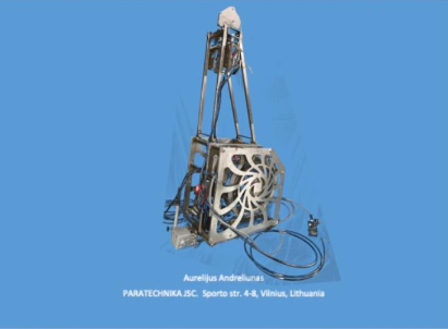
Paragliding Payout Winch
TowTechniks T2
Operating Manual
1. Introduction
The TowTechniks T2 is a payout winch for solo or tandem towing of paragliders. It can be easily mounted to a standard car tow hitch and operated via a handy remote control by the winch operator seated in the back of the tow vehicle.
2. Overview
2.1 Manufacturer details
| Manufacturer | |
| Name | TowTechniks |
| Contact | Gerard Backus |
| Address | Max-Planck-Straße 17, 52511 Geilenkirchen, Germany |
| info@towtechniks.com | |
2.2 Technical specifications
| Payout winch | |
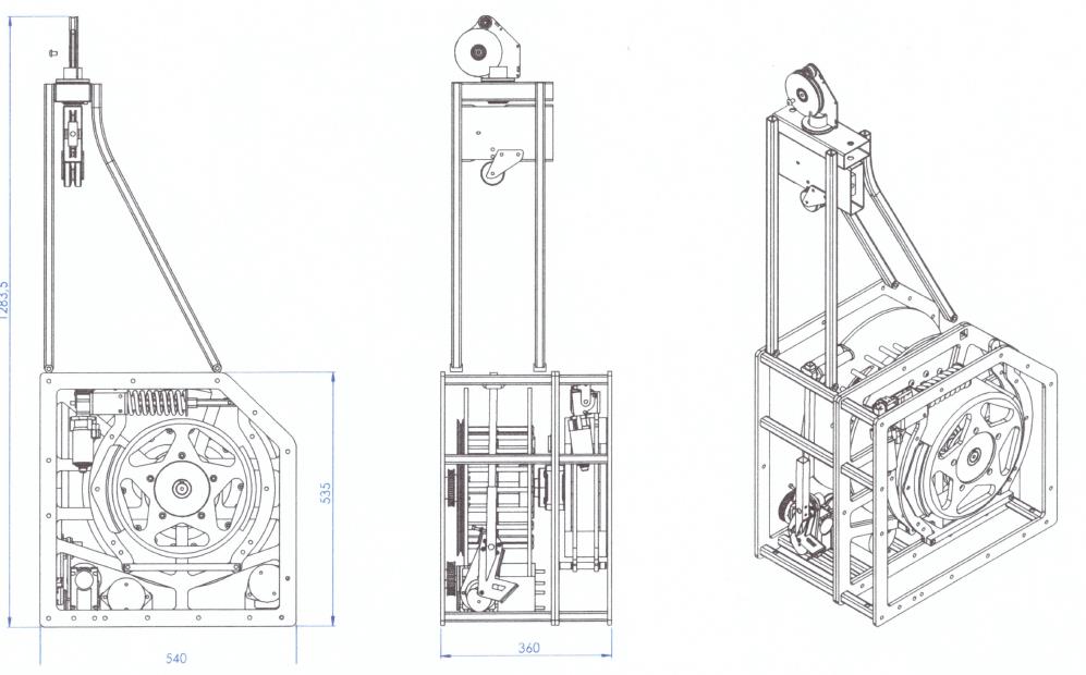
| Dimensions | Length: 540 mm, Width: 360 mm, Height: 1283.5 mm |
| Weight | 56 kg |
| Motor output | 1.6 kW |
| Current draw | max. 134 A |
| Tow line | |
| Line type | UHMWPE Dyneema |
| Maximum length | 1500 m |
| Diameter | 3 mm |
| Weight | 0.5 kg / 100 m |
| Breaking strength | 900 kg |
2.3 Materials list
| Payout winch |
| Anodised aluminium frame |
| Cast iron brake drum |
| Stainless steel ball bearings |
| Stainless steel cutter blade and release mechanism |
| Motors |
| 2 × 0.8 kW / 12 V DC motors |
| Ribbed v-belt drive |
| Power cable, control electronics |
| Tow line |
| UHMWPE Dyneema, 3.0 mm diameter |
| Remote control |
| Display, controls and electronics in plastic housing, not waterproof |
3. Setting up the T2
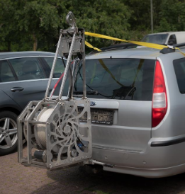
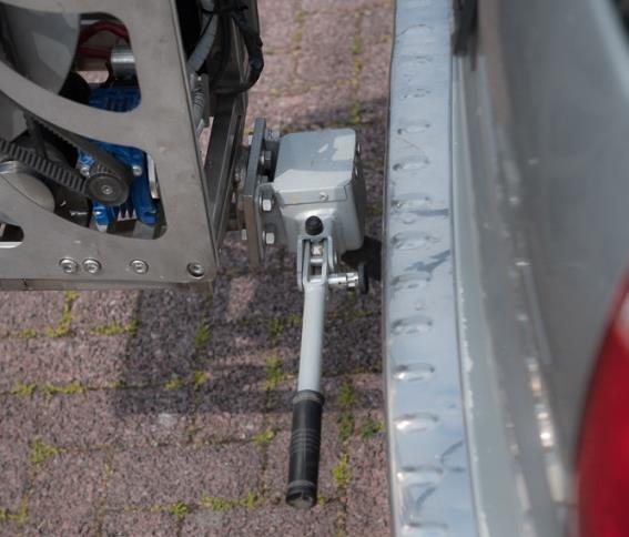
3.1 Mounting to the tow hitch
To mount the TowTechniks T2, place the winch onto the tow hitch with the mounting lever in the vertical position. Once the winch is correctly positioned, rotate the mounting lever to the horizontal position. Pull the safety pin slightly to release the lever, then lock it back in place with the pin.
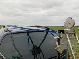
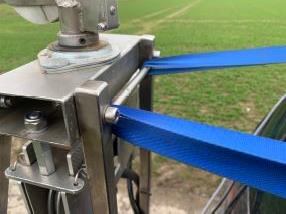
3.2 Securing the rotating tower
To relieve the load on the rotating tower, secure it with ratchet straps. Route the straps through the rear struts of the tower and through the roof rails of the vehicle, then tension them lightly. Secure the loose ends of the straps against flapping.
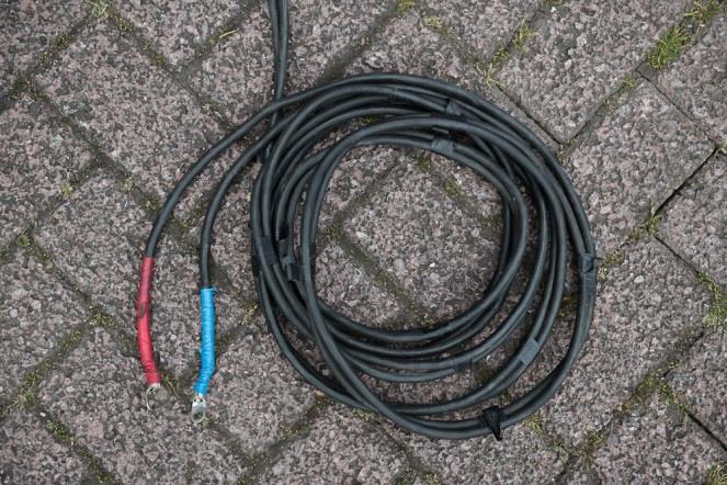
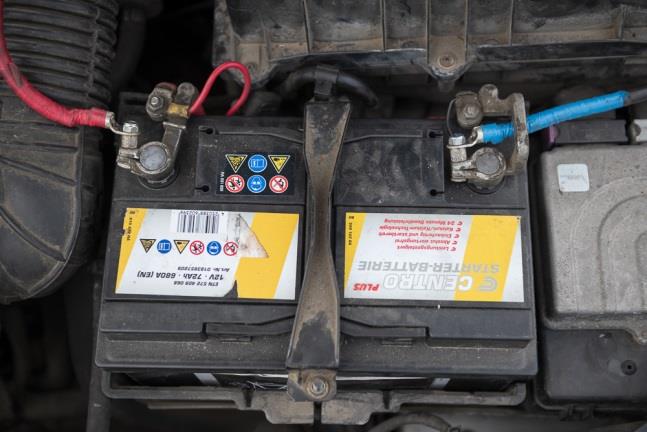
3.3 Connecting to the vehicle battery
The TowTechniks T2 must be connected directly to the car battery via the supplied cables. Route the cables securely from the rear of the vehicle to the battery — use the roof rails for routing, then along the A-pillar into the engine bay.
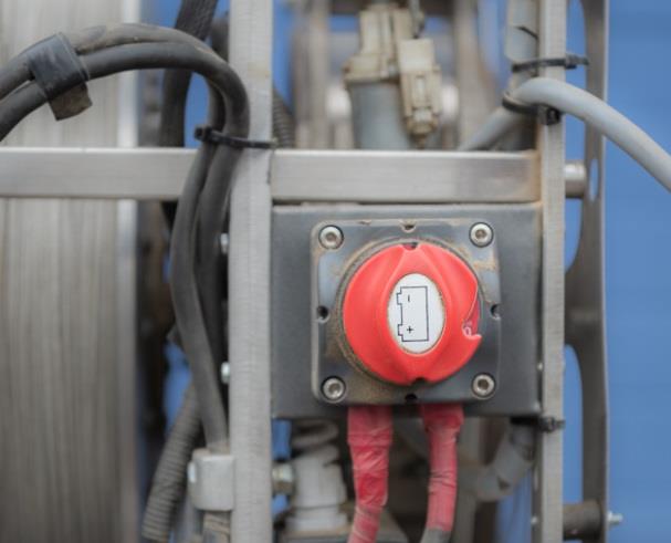
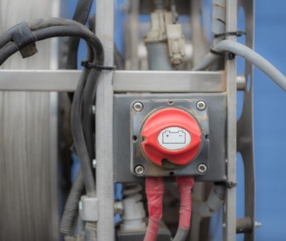
3.4 Main switch
The main switch is located on the rear of the winch and has two positions: “ON” and “OFF”.
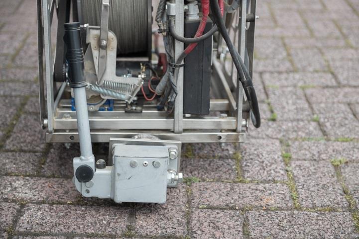
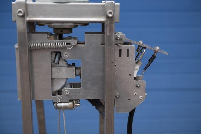
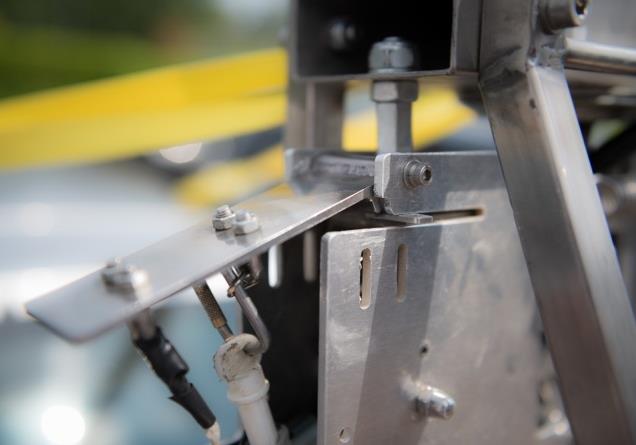
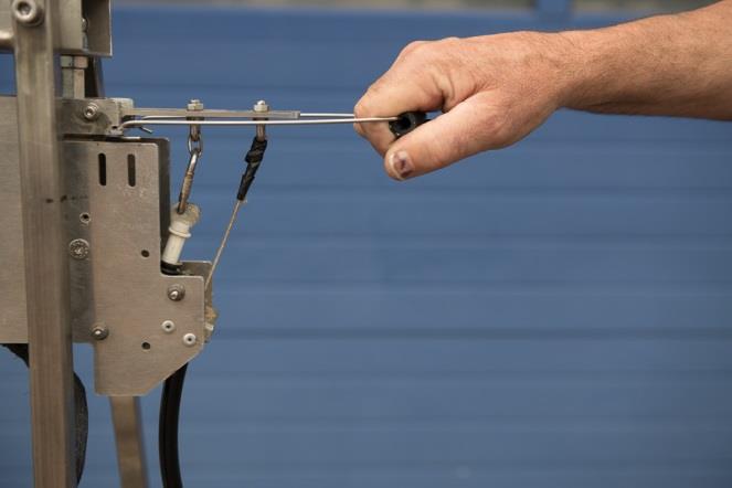
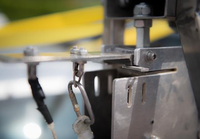
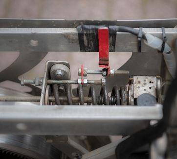
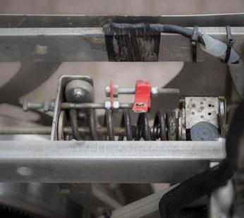
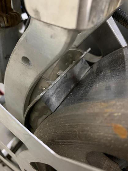
3.5 Cocking the line cutter
The line cutter is located inside the tower below the guide pulleys. It can be triggered mechanically or electrically. Use the cocking bracket to load it and check that it clicks securely into place.
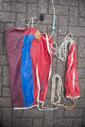
3.6 The tow rope assembly
The tow rope assembly consists of:
- Line parachute
- Weak link (1,500 N for solo and 2,000 N for tandem tows)
- Separation rope (8–10 m)
The complete tow rope assembly is made of low-stretch material and has a total length of approx. 25 m.
3.6.1 Tow line
The TowTechniks T2 uses UHMWPE DYNEEMA tow line, approved for paraglider towing. Breaking strength is 9,000 N. The maximum line length that fits on the drum is 1500 m and must not be exceeded. Dyneema line is repaired by splicing (see Ch. 5.1). The tow line connects to the tow rope assembly.
3.6.2 Line parachute
The line parachute is matched to the T2 by the manufacturer and is part of the winch type approval. It must not be replaced by a different line parachute or modified without a DHV change application.
3.6.3 Kite drogue
The TowTechniks T2 additionally uses a kite drogue which, after release, helps to reel in the line in an approximately twist-free and controlled manner, thereby reducing wear on the tow line.
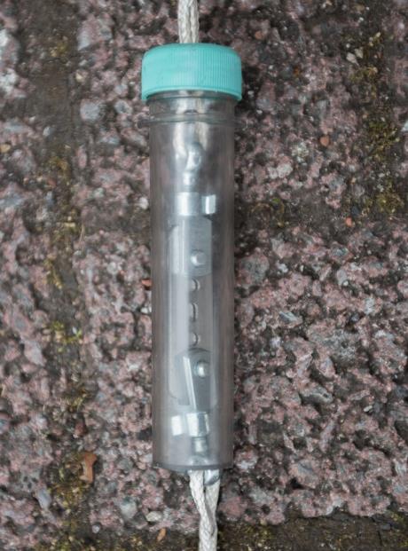
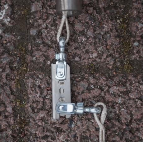
3.6.4 Weak link
The TowTechniks T2 uses a weak link with a rated breaking load of 150 kg for solo tows and 200 kg for tandem tows. The weak link must be DHV-approved and forms part of the type approval. Unapproved weak links must not be used.
- Weak links must be replaced per manufacturer instructions, typically after 200 tow starts.
- To prevent unintentional re-use, the worn weak link should be destroyed and disposed of.
- Before each tow session, check the weak link by pushing the two shackles together. If the shackle pin holes are worn, replace the weak link insert.
3.6.5 Separation rope
When using a low-stretch separation rope (e.g. Dyneema), no protective sleeve is required. The length of this rope is designed to prevent the pilot from flying into the line parachute when tow tension drops suddenly. The separation rope length is 8–10 metres.
3.7 Remote control description
The remote control features the following displays and controls:
- Red trigger button for electric line release on top of housing
- Display shows current pull force in kg
- “S” indicates solo mode (max. pull force 100 kg)
- “T” indicates tandem mode (max. pull force 130 kg)
- Lower display area is reserved for future extensions
- Left LED shows drum rotation
- Right LED: red = maximum pull reached; green = zero pull
- White button: increase pull force by approx. 8 kg per press
- Black button: decrease pull force by approx. 8 kg; hold for approx. 5 seconds = force to zero
- Hold left button continuously: reel in line
Solo or tandem mode is selected with a toggle switch above the brake drum. Lever up = tandem tow; lever down = solo tow.
It is recommended to route the remote control cable and the mechanical cutter pull on the same side of the vehicle along the roof rails and through the side window into the cab, and to secure them.
The remote control gives the winch operator complete control of the winch, including line release. Both an electric trigger (button on top of remote) and a mechanical pull are available.
When the line is being paid out, an audible beep and a white flash of the left LED (Drum Rotation) occur with each drum revolution, allowing the operator to easily monitor line pay-out.
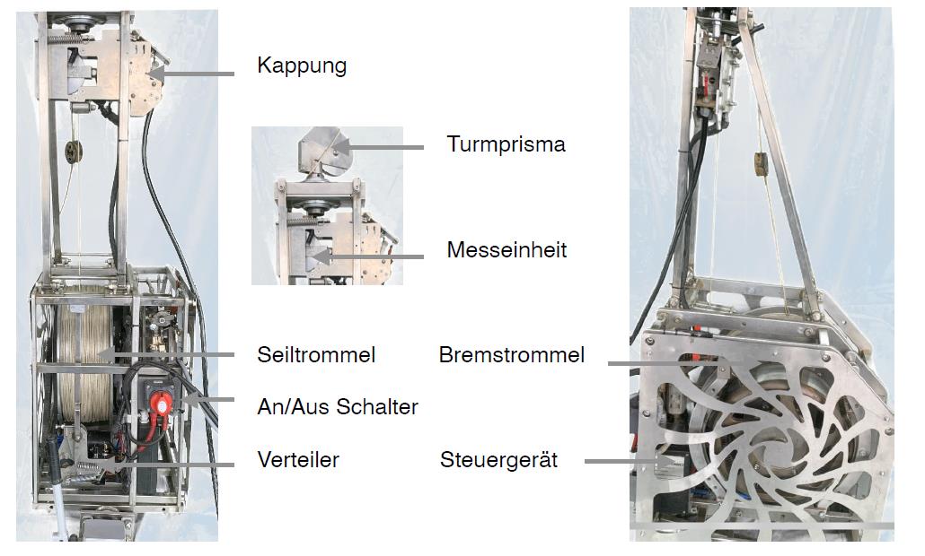
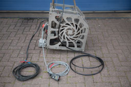
4. Assembly overview
Components of the TowTechniks T2: line cutter, tower prism, measurement unit, line drum, brake drum, on/off switch, distributor, control unit.
5. Notes and repairs
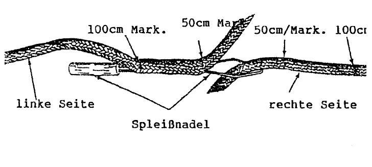
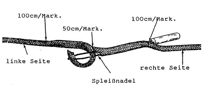
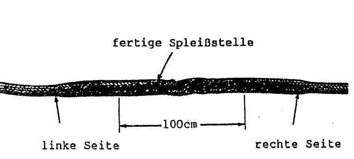
5.1 Repairing the tow line
All line repairs must be carried out in accordance with manufacturer instructions and are the sole responsibility of the winch operator. The winch operator must be familiar with the special repair technique.
When repairing synthetic tow lines, the line is typically spliced to ensure unobstructed line feed into the roller system.
5.2 Re-inspection
Every tow winch in Germany is subject to mandatory re-inspection. The owner is responsible for compliance. The inspection is carried out by the manufacturer or a DHV-approved inspection centre and documented with an inspection report.
5.3 Inspection intervals
Every tow winch with a quality seal or type approval number is subject to a regular 24-month re-inspection requirement.
5.4 Operation in Germany
Important: To keep the DHV quality seal valid, the winch must be inspected every 24 months by the manufacturer or the DHV inspection centre. Adjustments or repairs may only be carried out by persons certified by the manufacturer.
The following additional rules apply in Germany:
- The DHV winch operator regulations and flight operations order apply.
- Towing is only permitted at airspace-approved tow sites.
- A yellow rotating beacon must be visibly activated during towing.
5.5 Safety notice
Improper use or misuse of the TowTechniks T2 increases this risk considerably. Under no circumstances shall TowTechniks or the seller of the TowTechniks T2 be liable for injuries or damage to users or third parties caused by improper use of the winch.
If any aspect of using this equipment is unclear, please contact TowTechniks directly: info@towtechniks.com.
6. Further notes
6.1 Notes on towing
The TowTechniks T2 payout winch is designed for solo and tandem towing of paragliders. The joint flight operations order and the winch operator regulations of the Deutscher Hängegleiterverband e. V. (DHV, as of 02-2019) must be observed. Neither step-towing nor hang-glider towing is intended or permitted with the TowTechniks T2.
6.2 Special conditions / emergencies
6.2.1 Command “Halt Stop”
If the command “Halt Stop” is given before launch, the winch operator reduces pull to zero and the driver stops the tow vehicle. If “Halt Stop” is called during towing, the winch operator carefully reduces pull while the driver gradually reduces vehicle speed to allow the pilot to land safely.
6.2.2 Triggering the line cutter
If a fault occurs during towing that requires cutting the line, this can be done electrically via the red button on top of the remote control, or mechanically via the separate pull. In accordance with DHV guidelines, the line must be cut immediately if there is danger to the pilot, winch operator or third parties.
The cutter can be re-cocked with a bracket as described in Ch. 3.5. Check that it locks correctly into place.
6.2.3 Line break
A line break can occur at any point during towing without prior warning. For this reason, the winch operator and tow pilot must always fly in a way that allows the correct action to be taken immediately in the event of a line break (safety climb-out).
6.3 Environmental responsibility
When operating the TowTechniks T2, respect for nature and the landscape is required. This can be achieved for example by laying out the tow line carefully to avoid trampling farmland or damaging crops.
Since no oils or lubricants are required to operate the winch, there is no risk of contaminating paths or soil. As an additional protective measure, it is recommended to lay out sturdy tarpaulins to protect the ground and paragliders, especially during launch preparation.
6.4 Storage and transport
The TowTechniks T2 should be stored upright on a firm surface, kept dry. Due to its weight and size, it should be carried by 2 persons, using the lower struts of the winch as handles.
6.5 Disposal
The TowTechniks T2 is made of high-quality materials which must be properly separated and fed into the recycling cycle when disposed of. Material separation must be carried out by qualified personnel, a specialist company, or the manufacturer.
7. Maintenance
7.1 Motors
The motors are maintenance-free.
7.2 Line guide roller system
Before each tow session, check that all rollers run smoothly. In case of faults or damage, replace the affected component.
7.3 Line cutter
Check that the cutter blade moves freely and inspect the cutting edge. If the cutting edge shows significant notching, replace it to ensure reliable function. Before each session, test the cutter: cock it, insert a scrap piece of line, trigger it — the line must be cut completely through.
7.4 Line winding unit
The line winding unit is maintenance-free.
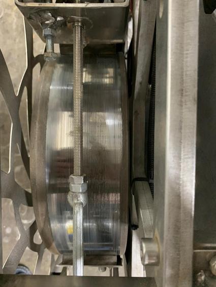
7.5 Brakes
After approx. 2,000 tows, check the set pre-tension of 5–8 kg and adjust if necessary. New brake pad thickness is approx. 10 mm. If a visual inspection shows thickness below 3 mm, replace all 6 brake shoes on both half-shells.
7.6 Tow rope assembly
Check lines and attachment eyes for wear and replace if necessary. Replace the weak link after wear or after 250 tow cycles. Inspect the line parachute and its lines for damage and replace if necessary. In addition, check all connection points regularly.
Original document: The complete operating manual V 2.2 is available as a PDF from the DHV.
Download DHV operating manual B_05-0042-20 (PDF)More about the T2: Technical specs and videos on the home page · Remote control in detail · Photo gallery · Contact